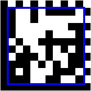

Introduction to Datamatrix Datamatrix falls under the 2D barcoding symbology. The traditional barcode symbologies were typically 1-Dimensional and carry much restriction. It varies directly with the amount of data being coded and as data collection evolves, the challenge is to code a vast amount of information onto a relatively small real estate. Hence, the popularity of adopting a 2-Dimensional symbology. Datamatrix were further popularized as the United States Department of Defense aims aggressively to have all components in an aircraft being marked with a Datamatrix symbology within a tight timeline. Datamatrix were invented by I.D. Matrix which were later bought over by Computer Identics and renamed to CI Matrix. CI Matrix was in turned bought over by RVSI and became RVSI Acuity CIMatrix. In 2005, Siemens Energy and Automation acquired and owns, RVSI Acuity CIMatrix. The following is a detailed description of the most commonly used bar code symbologies. Construction of a Datamatrix Barcode1) A Typical layout would be having 2 sides of the matrix to form a "L" shaped and the other 2 sides having alternating black and white elements. 2) Quiet Zone as in all barcode symbology is necessary. The minimum quiet zone requires is at least one element size at all the fours sides of the symbol. However, for ease of scanning, it is always recommended to have as much quiet zone as possible. A rule of thumb would usually hovers around 4 elements size. 3) The border (sides of the symbol) is also known as the finder pattern and is being use to determine the size, orientation and symbol distortion. 4) Symbol sizes ranges from a 10X10 up to 144X144 5) Maximum size capacity => more than 2000 for alphanumeric, more than 3000 for numerical.
6) The blue square contained the data encoded. 7) All Datamatrix barcode are encoded with an Error Correction Code (ECC) 8) Datamatrix first adopted the Convolutional Coding and were later being replaced by the Reed-Solomon error correction. 9) However, the Convolutional Coding is currently obsolete and hence, some scanners might not be able to scan something that had an ECC not equal to 200. How good is your Datamatrix ?Getting it to be printed marked or etched may not guaranteed a complete readability. Certain precautions had to be taken in order to ensure the information being encoded within the symbology could be portable and be interpreted regardless on what external hardware devices is used to decodes it. Hence, the industry had came out with certain verifications parameters to ensure the quality of the symbology. The common reference would be the ISO/IEC 15415. We will discuss over here what are the critical parameters being assessed. Symbol Contrast
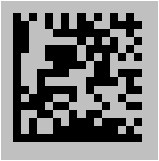
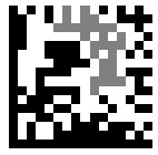
Symbol contrast actually measures the reflectance between the dark and light regions of the symbology. Picture shows a low contrast symbol (Black with grayish background). With low symbol contrast, some readers might have difficulty in reading the symbol. Fixed Pattern Damage
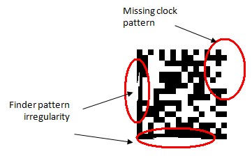
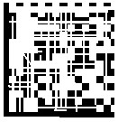
The fixed pattern of the symbol defines, locate, orientate and mapping the symbol. Any damage to the fixed pattern (clock or finder) will inevitably deter good read. Hence, It is essential to maintain a good fixed pattern Axial Non-Uniformity
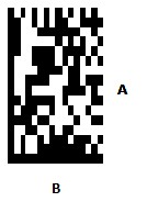
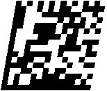
This measures both the uniformity of the "A" and "B" axis, The higher the deviation, the lower the Axial Non-Uniformity value and the harder it is for a reader to decode the symbol. Notice that the Axis A is much longer then the Axis B resulting in a rectangular element instead of a square. Grid Non-Uniformity
Grid non-uniformity measures the vector deviation from an ideal grid and the bigger the deviation from the ideal, the more difficult it is for a reader to decode the symbol. Thus, it is also essential that any vector deviation is kept at a minimum. Modulation
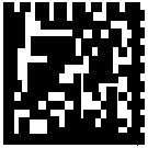
Modulation refers to the ability to discrimination between the dark and the light elements. Notice that the picture on the left had some of its dark elements very much different in color/reflectance to the rest. This will deter a good modulation value. Unused Error Correction CapacityAll Datamatrix symbologies would contain an error correction code. The amount of error correction to a symbology, though assist in the final decoding of the information but inevitably would means that the data in the symbol is destroyed. The higher the destruction would calls for a higher error correction and in return reduced the unused error correction capacity. With a low unused error correction capacity, it would readily mean that the barcode were badly printed or constructed. Print GrowthOver Print Under Print
Print Growth refers to the larger or smaller from the ideal or expected size of the symbology. When a symbol is printed, depending on the amount of ink applied, it may results as per above => over print or under print. Pixels Per Element
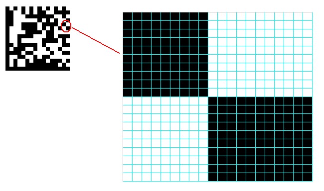
To ensure reliable and consistent verifications, a symbol had to contains a minimum of 10 Pixels per element. The above shows elements with at least 10 pixels on each single element. Common ApplicationsAerospace, DOD (US) - Typically marked onto components through industrial ink-jet, dot-pen marking, laser marking, and electrolytic chemical etching (ECE). Product Marking - On labels or direct marking in products, Production traveler that can contains huge information. Logistics - On packing list, Shipping List, Delivery Orders and Acknowledgement forms. Pharmaceutical /Lab - Patient's records, Research Information, Marking of Vials and Chemicals. |


